
PSWGT-300 Power jack 300W Grid Tie Inverter - Microinverter - Repair
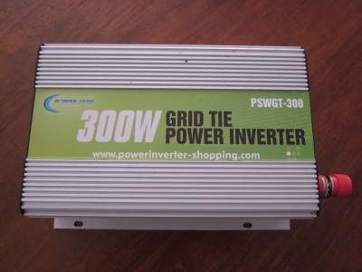
Power Jack (henceforth referred to as PJ), a Chinese a brand that has risen to notoriety in the past few years, has been churning out cheap (both price and quality) grid tie inverters.
A micro-inverter for the masses
The amazingly cheap prices for Power Jack GTIs meant that almost every man and his dog can afford to invest in a small (micro?) scale grid-feed solar PV system. In fact, products such as this are commonly used in the guerrilla solar movement.
Simply add some solar panels and cables and that's all you'll need to start your green initiatives. There's no need to spend thousands on a much larger, professionally installed system, nor the need to worry about paperwork and having to deal with the utility company in order to get the system connected and switched on. Instead, you start small, with minimal outlay. Should you decide to expand, you can do so gradually.
These PJ inverters are now widely available, especially on ebay. At the time of writing (2011), a typical 300 watt unit costs anywhere from $120 to $200.
A small system feeding up to 130 watts back into the grid via two 80 watt panels with a PSWGT-300 could cost as little as $600.
Efficiency & RFI
Out of the box, these inverters don't quite live up to the manufacturer's efficiency claims of 90% - 95%. The explaination for this is simple: although there is a 4,700uF 35v capacitor across the DC rails (which is fine for the high frequency chopper), the power draw on the secondary (AC) side runs at low frequency (50 or 60Hz). This low frequency severely 'rattles' the 4,700uF cap, leading to efficiencies of around 80%. Worse still, when connected to solar PV panels using more than a few meters of cable, efficiency suffers even more. Solar panels are basically a high impedance voltage / current source, and the impedance of the cables don't help.
There is a simple solution to this: fit a 10,000uF (or higher) capacitor across the solar PV rails, as close as possible to the DC input terminals of the inverter. Ideally, the 10,000uF capacitor should be installed into a spare space inside the GTI's enclosure, using heavy flyleads to connect it to the DC rails. The capacitor provides the much needed low-imedance DC source to let the inverter run closer to its rated efficiency. Even better, use a combination of both an internally fitted capacitor, as well as one across the PV rails outside the inverter. Some have suggested using capacitors as large as 250,000uF for wind turbines, which may seem extreme, but for anything over a few hundred watts, it makes a big difference.
Radiofrequency Interference (RFI) can also be a problem with these units. They were designed to be cheap rather than to pass stringent EMC regulations with flying colours. The AC side is generally OK, but the DC side on a stock standard PJ GTI usually has RFI pouring out, made worse by the cable run to the solar panels (this acts as an antenna; the longer the wire, the worse it is). Some have reported that it 'wipes out AM radio' within a 100 meter radius.
The RFI fix is also a simple affair - install bypass capacitors between the DC rails and the ground (case). Grab two ceramic, MKT or greencap capacitors with a value of at least 0.1uF 100v. Use one capacitor per positive and negative terminal, with one side connected to the terminal, and the other end tagged to the case. Once installed, RFI is virtually cured.
Having said that, the PJ GTI does have a 4.7nF capacitor between the earth/case and negative DC rail, but this is far too small to provide adequete RFI supression. And the supression capacitor is located more towards the AC side, leaving the DC side inadequetely supressed.
Known Problems
These GTIs are well known for 'going bang', blowing their mains fuse due to the MOSFETs shorting out on the high voltage side. The reason for this is due to voltage spikes causing the tracking to go out of sync, causing the MOSFETs to push the wrong way against the mains power source and subsequently blowing them. Switching the AC power to (or plugging/unplugging) the GTI whilst the DC source is present is similar to voltage spikes and there is every chance the MOSFETs will blow.
Always disconnect the DC side before turning on/off the AC side. If there is a grid blackout, the anti-islanding function will work as per usual, but the risk of blowing the MOSFETs will be low due to other loads (appliances) on the circuit pulling the AC line voltage to zero.
Some 300W units do not come fitted with a cooling fan. This severely limits their power handling capacity before overheating. In this case, they should be de-rated to not have more than 100 watts of solar PV input.
Regardless of the rated capacity, it is recommended to not exceed 150 watts of input. Higher input wattages only lead to slightly increased AC output, with most of the energy wasted as heat. Efficiendy drops off steeply above 200W. With 120 watts flowing through, the cooling fan can run continuously. This is a sure sign the inverter is wasting energy.
Important note: Due to the below-average build quality and cost-cutting measures (which sacrifice reliability and safety), PJ products are NOT recommended for the average DIYer unless you are experienced in electronics and repair (particularly in the field of switchmode power supplies). Even their website is full of 'Chinglish', with many Ebay sellers blissfully copying the atrocious product literature for use in their item description. Lines such as "How to Install?" and "How to take away?" are comical and confusing when a simpler "How to Plug in" and "How to unplug" would suffice.
Nonetheless, experienced electronics personnel will still come across some hurdles. Power Jack took extreme measures to protect their designs, which includes sanding/scrubbing the tops of all ICs to remove identifying marks, rendering repair difficult. Sneaky tactics such as this are designed to make the (already unreliable) inverter a 'throw-away' item - i.e. if it breaks, you'll need to buy a new one.... Buyer beware!
Repair
After a failure of the MOSFETs, repair is possible. Replacing the offending MOSFET usually restores the inverter's operation, although anecdotally, they have a tendancy to blow again after some time. Some say the inverter is more reliable on 110v than on 240v grids. It could be due to the voltage rating of the MOSFETs. 110v versions may use 500v rated MOSFETS, and the 220v version uses 600v MOSFETS. Where possible, use 900V MOSFETs if available.
When replacing MOSFETs (especially on the AC side) it is prudent to replace them as a group of 4, for when one blows, it can weaken the remaining good FETs, rendering them more likely to blow.
Repair may be worthwhile if you have the necessary experienced and/or knowledge. For what they're worth, you couldn't even buy all the components for any less than the selling price of a PJ inverter. PJ inverters can be of value provided the user knows how to maintain and repair them.
currywurst, Tue, 22 May 2012 06:04 pm: Reply
gab, Fri, 27 Jul 2012 09:23 pm: Reply
Luke Tanti, Fri, 09 Nov 2012 06:23 am: Reply
rlk, Fri, 02 Aug 2013 06:27 pm: Reply
marwan, Thu, 16 Jan 2014 12:59 am: Reply
Peter, Thu, 08 May 2014 12:20 pm: Reply
Peter, Sat, 31 May 2014 07:27 am: Reply
Peter, Sat, 31 May 2014 08:16 am: Reply
Steven, Mon, 09 Jun 2014 11:27 pm: Reply
gman, Fri, 22 Aug 2014 12:22 pm: Reply
Fernando, Mon, 15 Sep 2014 04:39 pm: Reply
John, Wed, 17 Sep 2014 08:09 am: Reply
Paul, Thu, 18 Sep 2014 06:04 pm: Reply
luisascencio, Wed, 11 Mar 2015 06:50 am: Reply
Marcos, Mon, 01 Jun 2015 12:00 am: Reply
Geert, Mon, 18 Apr 2016 04:27 am: Reply
Terry in Ohio, Fri, 10 Jun 2016 05:25 am: Reply