
Other > PZEM-016 with Arduino PZEM-014 RS485 Modbus
In 2017/2018, Peacefair released a number of cheap energy meter modules. These are widely available from China via Ebay, Banggood, Alibaba etc. Many types are available, ranging from modules with an integrated display through to displayless types designed for integration with other systems.
The variant we are looking at here is equipped with a RS485 interface and conforms to the Modbus RTU specifications for data communications. There are two subvariants of this model: the 014 is rated to 10 amps and contains an internal shunt, whilst the 016 is rated for 100 amps and includes an external current transformer.
These are cheap devices capable of remarkably accurate energy monitoring. All the basics are covered such as voltage, current and power (watts). As well, it includes line frequency (in Hertz), power factor and a resettable energy accumulator (Wh).
Basic concept
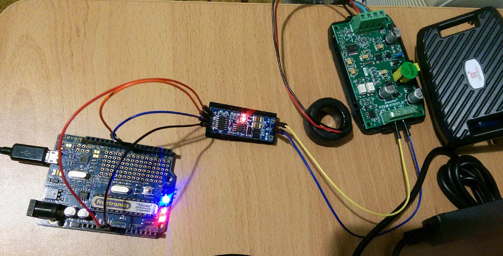
This article describes using an Arduino to read and process data from the PZEM-014 / -016. The following is required:
- PZEM-014 or -016
- Arduino Uno or compatible
- Serial TTL to RS485 converter
The TTL-485 converter module can easily be bought from Ebay.
To communicate with the PZEM, we will utilise the ModbusMaster library. This simplifies the process of sending Modbus commands to the device and makes data retrieval a snap. ModbusMaster contains all the necessary error handling when sending or receiving Modbus commands.
The PZEM has a built-in non-volatile energy accumulator (in Watt Hours). The value is maintained when the unit is unpowered, and can only be reset by sending a specific Modbus command.
We will be utilising SoftwareSerial on the arduino to communicate with the PZEM, leaving the native serial available for outputting to the PC or other purposes.
Connection Diagram
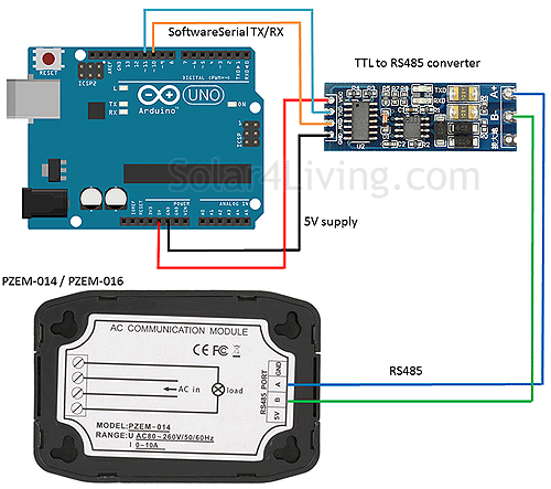
At only 9600 baud, the RS485 connection can be up to 1200 metres using twisted pair cable. The PZEM can be located in close proximity to the energy consuming equipment whilst the Arduino can be located centrally.
Warning: Whilst the RS485 interface of the PZEM is isolated from the mains voltage, the rest of the PZEM circuitry is at mains potential. If you remove the PZEM board from it's casing, take extreme care.
Arduino Sketch
/*
An Arduino Sketch for reading data from a PZEM-014 or PZEM-016
Uses this library: http://4-20ma.io/ModbusMaster/
*/


#include <ModbusMaster.h>
#include <SoftwareSerial.h>

SoftwareSerial pzemSerial(10,11); //rx, tx
ModbusMaster node;
static uint8_t pzemSlaveAddr = 0x01;
#define LEDPIN 13

void setup() {
  pzemSerial.begin(9600);
  Serial.begin(9600);
  //resetEnergy(pzemSlaveAddr);
  node.begin(pzemSlaveAddr, pzemSerial);
  pinMode(13, OUTPUT);
  digitalWrite(LEDPIN,0);
}

/*
RegAddr Description                 Resolution
0x0000  Voltage value               1LSB correspond to 0.1V
0x0001  Current value low 16 bits   1LSB correspond to 0.001A
0x0002  Current value high 16 bits
0x0003  Power value low 16 bits     1LSB correspond to 0.1W
0x0004  Power value high 16 bits
0x0005  Energy value low 16 bits    1LSB correspond to 1Wh
0x0006  Energy value high 16 bits
0x0007  Frequency value             1LSB correspond to 0.1Hz
0x0008  Power factor value          1LSB correspond to 0.01
0x0009  Alarm status  0xFFFF is alarm,0x0000is not alarm
*/

void loop() {
  uint8_t result;
  digitalWrite(LEDPIN,1);
  result = node.readInputRegisters(0x0000, 9); //read the 9 registers of the PZEM-014 / 016
  digitalWrite(LEDPIN,0);
  if (result == node.ku8MBSuccess)
  {
    float voltage = node.getResponseBuffer(0x0000) / 10.0;

    uint32_t tempdouble = 0x00000000;

    float power;
    tempdouble |= node.getResponseBuffer(0x0003);       //LowByte
    tempdouble |= node.getResponseBuffer(0x0004) << 8;  //highByte
    power = tempdouble / 10.0;


    float current;
    tempdouble = node.getResponseBuffer(0x0001);       //LowByte
    tempdouble |= node.getResponseBuffer(0x0002) << 8;  //highByte
    current = tempdouble / 1000.0;

    uint16_t energy;
    tempdouble = node.getResponseBuffer(0x0005);       //LowByte
    tempdouble |= node.getResponseBuffer(0x0006) << 8;  //highByte
    energy = tempdouble;

    Serial.print(voltage);
    Serial.print("V   ");

    Serial.print(current);
    Serial.print("A   ");

    Serial.print(power);
    Serial.print("W  ");

    Serial.print(node.getResponseBuffer(0x0008));
    Serial.print("pf   ");

    Serial.print(energy);
    Serial.print("Wh  ");
    Serial.println();

  } else {
    Serial.println("Failed to read modbus");
  }
  delay(2000);
}

void resetEnergy(uint8_t slaveAddr){
  //The command to reset the slave's energy is (total 4 bytes):
  //Slave address + 0x42 + CRC check high byte + CRC check low byte.
  uint16_t u16CRC = 0xFFFF;
  static uint8_t resetCommand = 0x42;
  u16CRC = crc16_update(u16CRC, slaveAddr);
  u16CRC = crc16_update(u16CRC, resetCommand);
  Serial.println("Resetting Energy");
  pzemSerial.write(slaveAddr);
  pzemSerial.write(resetCommand);
  pzemSerial.write(lowByte(u16CRC));
  pzemSerial.write(highByte(u16CRC));
  delay(1000);
}

void changeAddress(uint8_t OldslaveAddr, uint8_t NewslaveAddr)
{
  static uint8_t SlaveParameter = 0x06;
  static uint16_t registerAddress = 0x0002; // Register address to be changed
  uint16_t u16CRC = 0xFFFF;
  u16CRC = crc16_update(u16CRC, OldslaveAddr);
  u16CRC = crc16_update(u16CRC, SlaveParameter);
  u16CRC = crc16_update(u16CRC, highByte(registerAddress));
  u16CRC = crc16_update(u16CRC, lowByte(registerAddress));
  u16CRC = crc16_update(u16CRC, highByte(NewslaveAddr));
  u16CRC = crc16_update(u16CRC, lowByte(NewslaveAddr));

  Serial.println("Changing Slave Address");

  pzemSerial.write(OldslaveAddr);
  pzemSerial.write(SlaveParameter);
  pzemSerial.write(highByte(registerAddress));
  pzemSerial.write(lowByte(registerAddress));
  pzemSerial.write(highByte(NewslaveAddr));
  pzemSerial.write(lowByte(NewslaveAddr));
  pzemSerial.write(lowByte(u16CRC));
  pzemSerial.write(highByte(u16CRC));
  delay(1000);
}
Notes
Every two seconds, the sketch sends a Modbus command to request the first 9 input registers. The response buffers are reassembled and printed to the serial output for display.
Note that the ModbusMaster library does not incorporate a Modbus function (0x42) for resetting the cumulative energy value in the PZEM, so I have written some custom code to send the reset command.
From here, the basic concept can easily be combined or integrated into another project for energy monitoring or control purposes. For example, it is possible to have the Arduino hundreds of meters away from the PZEM, and incorporate an LCD to display the power information.
Frigos, Tue, 13 Aug 2019 06:17 am: Reply
Radek, Thu, 15 Aug 2019 05:10 pm: Reply
STEPHEN CLAPSHOE, Thu, 27 Feb 2020 08:04 pm: Reply
Chanu, Tue, 14 Jul 2020 11:15 pm: Reply
Bars, Mon, 17 Aug 2020 08:22 am: Reply
Toni, Thu, 01 Oct 2020 05:34 am: Reply
Mike, Fri, 25 Dec 2020 03:37 am: Reply
Rob, Fri, 14 Jan 2022 01:11 am: Reply
Rob, Tue, 18 Jan 2022 05:43 am: Reply
Corrado, Fri, 10 Feb 2023 07:03 pm: Reply
Corrado, Sun, 26 Feb 2023 09:53 am: Reply
phinit, Thu, 06 Mar 2025 05:21 pm: Reply